- 您现在的位置:买卖IC网 > Sheet目录1991 > CS5346-CQZR (Cirrus Logic Inc)IC ADC AUD 103DB 200KHZ 48-LQFP
18
DS861PP3
CS5346
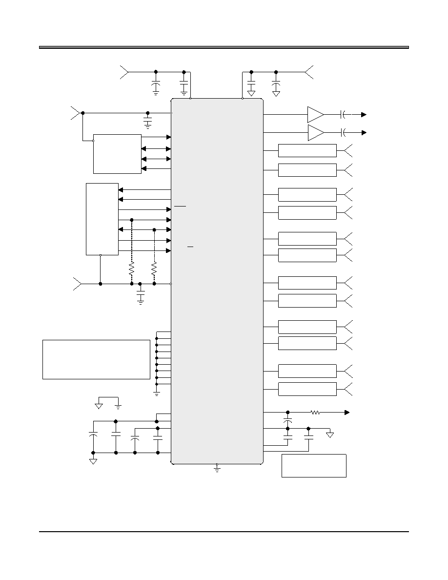
4. TYPICAL CONNECTION DIAGRAM
VLS
0.1 F
+3.3V
to +5V
DGND
VLC
0.1 F
+3.3V
to +5V
SCL/CCLK
SDA/CDOUT
AD1/CDIN
RST
2 k
See Note 1
AD0/CS
Notes:
1. Resistors are required for IC control port
operation.
2. The value of RL is dictated by the microphone
cartridge.
3. See Section 5.5.1.
Micro-
Controller
Digital Audio
Capture
LRCK
SDOUT
MCLK
SCLK
PGAOUTA
PGAOUTB
2.2nF
AFILTA
AFILTB
OVFL
2.2nF
3.3 F
47 F
0.1 F
VQ
FILT+
10 F
AGND
2 k
INT
47 F
AIN1A
Left Analog Input 1
AIN1B
Right Analog Input 1
AIN2A
Left Analog Input 2
AIN2B
Right Analog Input 2
AIN3A
Left Analog Input 3
AIN3B
Right Analog Input 3
AIN4A/MICIN1
Left Analog Input 4
AIN4B/MICIN2
Right Analog Input 4
AIN5A
Left Analog Input 5
AIN5B
Right Analog Input 5
AIN6A
Left Analog Input 6
AIN6B
Right Analog Input 6
MICBIAS
AGND
0.1 F
NC
10 F
+3.3V
0.1 F
10 F
0.1 F
VA
VD
+5V
RL See Note 2
CS5346
Analog Input 3
VQ
AFILTA and AFILTB
capacitors must be C0G or
equivalent
Figure 7. Typical Connection Diagram
发布紧急采购,3分钟左右您将得到回复。
相关PDF资料
CS5351-BZZ
IC ADC AUD 108DB 204KHZ 24-TSSOP
CS5361-DZZ
IC ADC AUD 114DB 204KHZ 24-TSSOP
CS5364-CQZR
IC ADC 4CH 114DB 216KHZ 48-LQFP
CS5366-DQZR
IC ADC 6CH 114DB 216KHZ 48-LQFP
CS5368-DQZ
IC ADC 8CH 114DB 216KHZ 48-LQFP
CS5381-KSZ
IC ADC AUD 120DB 192KHZ 24-SOIC
CS53L21-CNZR
IC ADC STEREO 24BIT 98DB 32-QFN
CS5509-ASZR
IC ADC 16BIT SGL SUPP 16-SOIC
相关代理商/技术参数
CS5346-DQZ
功能描述:模数转换器 - ADC 103dB 24Bit 192kHz Stereo Audio ADC RoHS:否 制造商:Texas Instruments 通道数量:2 结构:Sigma-Delta 转换速率:125 SPs to 8 KSPs 分辨率:24 bit 输入类型:Differential 信噪比:107 dB 接口类型:SPI 工作电源电压:1.7 V to 3.6 V, 2.7 V to 5.25 V 最大工作温度:+ 85 C 安装风格:SMD/SMT 封装 / 箱体:VQFN-32
CS5346-DQZR
功能描述:音频数/模转换器 IC 103dB 24Bit 192kHz Stereo Audio ADC RoHS:否 制造商:Texas Instruments 转换器数量: 分辨率:16 bit 接口类型:I2S, UBS 转换速率: 信噪比:98 dB 工作电源电压:5 V DAC 输出端数量:2 工作温度范围:- 25 C to + 85 C 电源电流:23 mA 安装风格:SMD/SMT 封装 / 箱体:TQFP-32 封装:Reel
CS5349-000
制造商:TE Connectivity 功能描述:4110-10-340812
CS5349-BP
制造商:未知厂家 制造商全称:未知厂家 功能描述:Analog-to-Digital Converter, 16-Bit
CS5349-BS
制造商:未知厂家 制造商全称:未知厂家 功能描述:Analog-to-Digital Converter, 16-Bit
CS5349-KP
制造商:未知厂家 制造商全称:未知厂家 功能描述:Analog-to-Digital Converter, 16-Bit
CS5349-KS
制造商:未知厂家 制造商全称:未知厂家 功能描述:Analog-to-Digital Converter, 16-Bit
CS5351
制造商:CIRRUS 制造商全称:Cirrus Logic 功能描述:108 dB, 192 kHz, Multi-Bit Audio A/D Converter